MACHINERY AND EQUIPMENTS
VENDORS TO BE SELECTED AFTER DISCUSSION WITH THE CLIENT
BELOW ARE THE PREVAILING MARKET PRICE OF THE ITEMS (INCLUDING
1. IMPORTED CONTROLLED ATMOSPHER MACHINERY
2. REFREGIRATION PLANT AND MACHINERY
3. ELECTRICAL PANELS
4. PUFF PANELS
5. IMPORTED CA CHAMBER SLIDING DOORS
Considered import duties nil against EPCG licence for all imported items like CA Equipment, CA Doors. Client will submit EPCG for imported items for availing this benefit
(THIS PRICE QUOTATION IS PROVIDED TO US BY ONE OF OUR REPUTED MACHINERY VENDORS, THE COST WILL VARY AT THE TIME OF ORDER)
| Sr. No. | Description | Total Amount |
| PART A | ||
| 1 | Refrigeration Plant & Machinery | 7,80,00,000.00 |
| 2 | Ventilation System | |
| 3 | Humidification System | |
| 4 | Electrical Panel + Automation | |
| 5 | PUF Panels + Accessories | |
| 6 | CA Local Items | |
| Total Cost of A(Ex-Work) | 7,80,00,000.00 | |
| Low side Part B | Total Price | |
| 1 | Installation, Testing and Commissioning of Ref Systems, PUF Panels, Doors, CA Systems | 46,00,000.00 |
| Total Cost of Part B | 46,00,000.00 | |
| Part C (Imported Item Cost – With EPCG Licence) | Total Price | |
| 1 | Imported Controlled Atmosphere Machinery. | 2,45,12,000.00 |
| (Include: Sea Fright, Custom Clarence, transportation up to Site.) | ||
| 2 | Imported CA Chambers Sliding Doors | 99,80,000.00 |
| (Include: Sea Fright, Custom Clarence, Local Transportation up to site.) | ||
| Total Cost of Part C (FOB Site) | 3,44,92,000.00 | |
| Total Project Basic Cost (INR) | 11,10,92,000.00 | |
| Total Basic Cost of A and B (Ex-Works) | 7,96,00,000.00 | |
| GST 18% on Part A and B | 1,43,28,000.00 | |
| Total Cost with GST of Part A and B | 9,39,28,000.00 | |
| Appx Freight Cost | 46,90,000.00 | |
| Total Landed Cost Part A, B and C with EPCG Licence | 13,61,10,000.00 | |

1. EXCLUSIONS / CLIENT’S SCOPE
The following items are specifically excluded from our scope of supply and execution and shall be arranged/provided by the Client:
- Civil & PEB Works:
All types of civil and PEB works, including office buildings, labour rooms, weighbridge offices, compound walls, underground water storage tanks and other associated civil works. - Power, Water & Lighting:
Continuous availability of adequate power, water supply and proper lighting at the site throughout the execution and commissioning period. - Insurance & Safe Custody:
All types of insurance charges during and after execution of the project, including insurance and safe custody/security of materials and goods at site. - Billing through Associate Firms:
We reserve the right to split or raise the final bill, as required, through our associate firms. - Drainage & Water Piping:
Drainage arrangements in the plant room, make-up water piping, rainwater discharge arrangements and associated works. - Items Not Specifically Mentioned:
Any item, work, service, accessory or facility not specifically mentioned in our offer shall be considered outside our scope. - Design / Alternate Makes:
In case of any issue relating to availability or delivery of specified components, we reserve the right to modify the design or provide equivalent/alternate makes or components, without adversely affecting the performance and functionality of the project. - Electrical & Earthing Works:
Internet connection, stabilizers and allied electrical requirements; main incoming cable up to our switchboard; earthing works; earthing of panel boards, generator and other equipment; SEB/electricity supply to panel; generator-to-panel wiring; single-phase wiring with fittings inside and outside the cold rooms; switches, PF panels, capacitor fittings, machine foundations, generator set and allied accessories shall be in the Client’s scope. - Temporary Power & Price Escalation:
Temporary power/electricity charges during the execution period and any unavoidable or additional costs arising due to escalation/inflation in raw-material prices, fluctuations in exchange rates, or any other unforeseen price variation during project execution shall be borne by the Client. - Water Connection for Equipment:
Provision of water connection and related arrangements required for NSSPL-supplied equipment, if required, shall be in the Client’s scope. - Unloading of Materials:
Unloading of all materials, equipment and components at the project site shall be arranged by the Client. - Boarding & Security:
Boarding/accommodation facilities for our personnel shall be provided by the Client. Food arrangements shall be made by us. Security and safe custody of our manpower, materials and equipment at site shall be the Client’s responsibility.
Technical specifications of the proposed storage facilities:
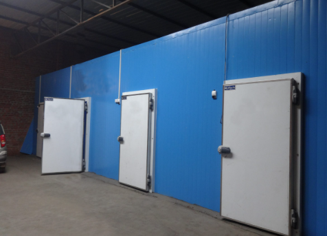
BASIC DESIGN DATA:
Total No. of Chambers 20 No’s.
Max. Inside Room Temp. +0.5 Deg C for CA Chamber
Max. Inside Room Temp. +2 Deg C for Corridor Area
Control Atmosphere Chamber 20 Nos.
Refrigerant R 717 (Ammonia with Glycol)
Commodity to be stored: Apple
CHAMBER DETAILS:
| Sr. No. | Chamber No. | Size of Chamber ( Mtr ) | Capacity As Per 4.4 Cu.Mtr / Ton | Method of Stacking | Type of Storage | ||
| L | W | H | |||||
| 1 | Ch – 1 | 14.15 | 6.60 | 11.80 | 250 | Wooden Bins | CA |
| 2 | Ch – 2 | 14.15 | 6.60 | 11.80 | 250 | Wooden Bins | CA |
| 3 | Ch – 3 | 14.15 | 6.60 | 11.80 | 250 | Wooden Bins | CA |
| 4 | Ch – 4 | 14.15 | 6.60 | 11.80 | 250 | Wooden Bins | CA |
| 5 | Ch – 5 | 14.15 | 6.60 | 11.80 | 250 | Wooden Bins | CA |
| 6 | Ch – 6 | 14.15 | 6.60 | 11.80 | 250 | Wooden Bins | CA |
| 7 | Ch – 7 | 14.15 | 6.60 | 11.80 | 250 | Wooden Bins | CA |
| 8 | Ch – 8 | 14.15 | 6.60 | 11.80 | 250 | Wooden Bins | CA |
| 9 | Ch – 9 | 14.15 | 6.60 | 11.80 | 250 | Wooden Bins | CA |
| 10 | Ch – 10 | 14.15 | 6.60 | 11.80 | 250 | Wooden Bins | CA |
| 11 | Ch – 11 | 14.15 | 6.60 | 11.80 | 250 | Wooden Bins | CA |
| 12 | Ch – 12 | 14.15 | 6.60 | 11.80 | 250 | Wooden Bins | CA |
| 13 | Ch – 13 | 14.15 | 6.60 | 11.80 | 250 | Wooden Bins | CA |
| 14 | Ch – 14 | 14.15 | 6.60 | 11.80 | 250 | Wooden Bins | CA |
| 15 | Ch – 15 | 14.15 | 6.60 | 11.80 | 250 | Wooden Bins | CA |
| 16 | Ch – 16 | 14.15 | 6.60 | 11.80 | 250 | Crates | CA |
| 17 | Ch – 17 | 14.15 | 6.60 | 11.80 | 250 | Crates | CA |
| 18 | Ch – 18 | 14.15 | 6.60 | 11.80 | 250 | Crates | CA |
| 19 | Ch – 19 | 14.15 | 6.60 | 11.80 | 250 | Crates | CA |
| 20 | Ch – 20 | 14.15 | 6.60 | 11.80 | 250 | Crates | CA |
| Total | 5000 | ||||||
Note: Please note that capacity shown is as per 4.4 Cu. M per ton. These capacities vary according to internal stacking system, product density and box size.
PART A
- Refrigeration Plant & Machinery
- Stand by Refrigeration Machinery
- Insulated Panel
- Panel Accessories & Installation with Doors
- Imported Gas Tightening Solution
- Floor Insulation
- Temperature Management System
- Humidification Management System
- Automatic Air Purger
- Electrical Work
- Automation System – PLC System with SCADA System
- Indian Items for CA Machinery
PART B
- Installation, Testing and Commissioning of PUF panels, Doors, floor insulation, Refrigeration System, CA Equipment Electrical Control Panel and Single phase lighting
PART C
- Imported Controlled Atmosphere Machinery
- Imported CA Chambers Sliding Doors

PART A
- WORKING REFRIGERATION PLANT & MACHINERY:
Refrigeration Systems are fully automatic and not dependent on operators.
- Reciprocating Compressor
Type: High Stage Direct Drive Compressor
Model: KCX 4
Driven Type: Direct
Capacity: 279 kW
Temperature: (Evap)-10 Deg c /(Cond)+40 Deg c
Refrigerant: R 717
Qty: 02 No’s Working
Each compressor is supplied with complete original OEM accessories
Capacity: 110 kW (IE2)/90KW
Type: 6 Pole, IE2, VFD Compatible Motor
Qty: 02 No’s Working
- Evaporative Condenser:
Condenser Capacity: 500 kW
Coil material: SS304L
Casing material: SS304
Basin Material: SS304
Sump Heater: Available
Type: Evaporative type
Fan Qty: 3 no’s
Pump Qty: 1 No’s
WBT: 28 WBT
Condensing temp.: 40 °C
Connection details:
Hot Gas supply 1 no
Air Purging 1 no
Safety valve
Connection 1 no
Oil drain 1 no
Qty: 2 No’s
Dual 500 kW condensers are proposed in place of a single 1000 kW unit to ensure redundancy, energy-efficient part-load operation, and uninterrupted plant performance
Main benefits:
- 100% redundancy for uninterrupted operation
- Energy-efficient part-Load performance during low Demand
- Operation Flexibility for maintenance without plant shutdown
- Improve Equipments life due to balance loading.
- GLYCOL CIRCULATION SYSTEM:
We have proposed most efficient glycol system with SS 304 ERW piping system. We used poly propylene glycol with inhibiters to maintain longer life of the system. The valves are control by PLC and provide perfect PID system to get best storage results.
- PHE Chillier
Type : PHE Type
Capacity : 227 TR (800 kW)
Flow rate : 300 CMH
Hot side : Propylene Glycol
Cold side : Ammonia
Qty : 1 No
- Accumulator:
Type Vertical
Design Temperature – 10 deg C
Shell thickness: 8 mm
Dish end thickness: 10 mm
Dimension:
Length 1500 mm
Diameter 900 mm
10% radiographic testing will be provided.
Qty : 1 No’s
- Buffer tank: (Glycol Tank) (considering 20 chambers)
For minus 10 Deg C system
MOC : MS Painted
Type : Horizontal – Cylindrical
Capacity : 23000 Litres
Length : 5000 mm
Outer Dia of Tank : 2400 mm
Thickness of Tank : 6 mm
Qty : 1 No
- Glycol Chillier Water Pump with VFD
Capacity : 30 kW @300 CMH @20 mwc
VFD : Yes
Qty : 2 No’s (1 Working + 1 Standby)
- Glycol Mono Block Pump for Chamber No. 1 to 20
Capacity : 2.2 kW @22 CMH @ 12 mwc
Total Qty : 20 No’s
- Glycol Mono Block Pump for Corridor No. A
Capacity : 2 HP @ 12 CMH @ 15 mwc
Total Qty : 2 Nos
- Glycol Mono Block Pump for Corridor No. B
Capacity : 2 HP @ 12 CMH @ 15 mwc
Total Qty : 1 No
- Glycol Pump for By-pass
Capacity : 2 HP @ 9 CMH @ 15 mwc
Qty : 2 No’s
- Refrigerant Control & Valves for Ammonia & Glycol:
We have proposed HP receiver with Dual Safety Valve and Pressure Gauge for Safe & efficient Working.
We have proposed frost free mechanical gauge glass on each HP & L.P. receiver.
- We have proposed this Valves & Accessories (Ball Valve, Check Valve, Stop Valve, Angle Valve, Strainer Filter, and regulating Valve, Single or Dual Safety valve, Drain Port Etc.) as per norms and requirement for safe operation.
- We have proposed a Backpressure Valve with each CA Chamber ACU for Controlling the Ammonia circulation and increase the efficiency without unnecessary heat loss.
- Qty: 1 Lot
- PPG:
First charge of PPG with inhibiters.
Qty: 1 Lot (First Charge Only)
- Glycol Pipe
MOC : SS 304 ERW
SCH : 10
Qty : 1 lot
- Drain Pipe for Cold room
MOC : PVC
Qty. : 1 Lot
- Pipe For Sprinkle Water On H.P
MOC : GI B Class
Qty. : 1 Lot
- Air cooling units
MOC: SS tube with aluminium fins
Type: Ceiling suspended
Qty: As per below mentioned
| Chamber | Capacity |
| ACU For CA APPLE Chamber no. 1 to 20 | 68 kW/Chamber |
| ACU For Corridor Area 1 | 74 kW Per Area |
| ACU For Corridor Area 2 | 30 kW Per Area |
Note: Air Cooling Units (ACUs) are strategically installed within the corridors to maintain a controlled temperature of approximately 2°C. These corridors are designed to act as thermal buffer zones, allowing temporary storage of produce during handling operations. This arrangement minimizes heat ingress into storage chambers, reduces thermal shock to the product, and helps in maintaining consistent product quality and shelf life.

Chamber ACU Technical Details:
- High Pressure Refrigerant Receiver: (considering 20 chambers)
Shell thickness: 12 mm
Dish end thickness: 14 mm
Liquid inlet and outlet connection
Dual stop valve with Dual safety valve connection
Purge valve connection
All nozzles are butt weld blank with cap at factory
Reflex type level gauge
Oil drain connection with sump
L type stand given for the receiver
Two coating of epoxy Paint & primer
Welding of Vessel: the refrigerant vessel shall be considered as class I vessel according to IS 2825 or 10% radiography for pressure vessels to be carried out in our factory
MOC SA516 GR70
Type Horizontal cylindrical
Connection details:
Liquid supply : 1 no
Air Purging : 1 no
Dual Safety valve : 1 no
Connection : 1 no
Liquid level transmitter : 1 no
Pressure Transmitter : 1 no
Liquid Laval Switch : 1 no
Temperature Transmitter : 1 no
Oil drain : 1 no
Qty : 1 No
- Refrigerant control valves:
- We shall provide valves and control devices that are strategically selected and positioned to ensure safe, reliable, and efficient operation of the ammonia refrigeration system.
- We shall provide Stop and stop-cum-check valves will be installed at key equipment interfaces (compressors, receivers, and pumps) for isolation and prevention of backflow, while check valves ensure unidirectional flow.
- We shall provide Strainers will be provided upstream of control valves to protect against contaminants.
- We shall provide Control valves such as solenoid, regulating, ICS, and BPRV (Back Pressure Regulating Valves) will be provided for all ACUs to maintain the desired evaporator pressure and stable temperature control.
- We shall provide Dedicated hot gas line valves and controls will be incorporated for defrost and system capacity management.
- Additionally, We shall provide safety valves, pressure gauges (PG), transmitters (PT), and level controls (HL/OL/LL) will be provided to ensure system protection, monitoring, and automatic control under varying operating conditions.
Qty: 1 Lot
Make: Danfoss
- Refrigerant Piping:
MOC: MS
Class: C Class
Qty: 1 Lot
- Pipe line insulation:
- We shall provide thermal insulation for all refrigerant piping, including suction lines, wet return lines, accumulators, and other low-temperature components, to prevent heat gain, condensation, and energy losses.
- Insulation shall be of high-quality nitrile rubber with adequate thickness as per line size and operating temperature, finished with aluminum cladding for mechanical protection and weather resistance.
- The insulation system will be designed to ensure vapor tightness, avoid moisture ingress, and maintain system efficiency, thereby ensuring stable operating conditions and long service life of the refrigeration system.
- The pipe line insulation will be carry out with 25 / 38 / 50 mm Thk Nitrial sheet & Aluminium cladding with suitable fasteners.
Qty. 1 Lot
- Pressure gauge, Temperature Gauge, Pressure Transmitter, etc
Qty: 1 Lot
- Hardware Fittings:
Includes: Gaskets / Bolts / Nuts / washer
Foundation bolts / Sealants / guide rails / base frame
Drive belts / pulley / Short bands / Flanges etc
Qty: 1 Lot
- Consumables:
Oil / Refrigerant / Grease / other accessories
Qty: 1 Lot (for first charge)
- STANDBY RECIPROCATING COMPRESSOR
Type: High Stage Direct Drive Compressor
Capacity: 279 kW
Temperature: (Evap)-10 Deg c /(Cond)+40 Deg c
Refrigerant: R 717
Qty: 01 No. Standby
Each compressor is supplied with complete original OEM accessories
Motor with VFD:
Capacity: 110 kW (IE2)/90Kw
Type: 01 No. Standby
Motor Make: Siemens/ABB
VFD Make Danfoss
- INSULATED PANEL:
The selection of insulated panels has been carried out based on the required internal room temperatures and application areas, with appropriate panel thicknesses chosen to ensure optimal thermal performance and energy efficiency. All panels shall be of continuous (factory-engineered) type, with pre-coated metal sheets on both external and internal surfaces for durability, hygiene, and corrosion resistance.
The quantities of panels have been estimated based on the available drawings and project layout. However, the final quantities may vary depending on actual site conditions, detailed engineering, and execution requirements. Accordingly, the quantities indicated in this offer are tentative and shall be finalized at the time of supply and installation.
Technical Data Sheet – 120 mm/80mm/50mm Thick PUF Insulated Panel
| Category | Parameter | Specification (120 mm/50mm Panel) |
| General | Panel Thickness | 120 mm/80mm/50mm |
| Panel Width | 1000 ± 2 mm | |
| Application | Wall & Ceiling (Internal / External) | |
| Panel Joint | Tongue & Groove (Airtight) | |
| Core Properties | Core Material | PUR / PUF |
| Density | 40 ± 2 kg/m³ | |
| Closed Cell Content | ≥ 85% | |
| Thermal Performance | Thermal Conductivity (K-Value) | ~0.023 W/m·K |
| Thermal Resistance (R-Value) | ~5.20 m²K/W | |
| U-Value | ~0.19 W/m²K | |
| Mechanical Properties | Compressive Strength | ≥ 110 kPa |
| Adhesion Strength | ≥ 100 kPa | |
| Dimensional Stability | Max. 2% | |
| Moisture Properties | Water Absorption | ≤ 2% |
| Water Vapour Permeability | < 5.5 ng/Pa·s·m | |
| Fire & Safety | Fire Classification | B3 (Self-extinguishable) |
| Burning Rate (Horizontal) | Max. 125 mm/min | |
| Blowing Agent | N-Pentane (CFC/HCFC/HFC free) | |
| Facing & Finish | Sheet Profile | Plain / Micro-rib |
| Sheet Thickness | 0.50 mm TCT | |
| Material | Pre-painted GI (PPGL) (This helps prevent corossion in better way as compared to PPGI) | |
| Coating | RMP/SMP, AZ-150 | |
| Color | RAL 9002 |
| Sr. No. | Description | Sq. Mtr |
| 1 | 120 mm thickness wall / ceiling Panel for 20 Chambers | 9420 |
| 2 | 80 mm thickness wall/ ceiling Panel for corridor | 2200 |
| 3 | 50 mm thickness wall/ ceiling Panel for cladding of colounm parts inside corridor | 1592 |
| Total | 13212 | |
- PANEL ACCESSORIES & INSTALLATION WITH DOORS:
Accessories for Airtight Panel Jointing System
To ensure complete air tightness of the Controlled Atmosphere (CA) chambers, special attention is given to panel jointing and sealing during installation. We provide and installs customized jointing accessories such as L-channels and matching profiles to achieve precise alignment and robust structural integrity of PUF panels.
All panel joints, interfaces, and connections are sealed continuously using high-quality silicone sealant applied along the full length of the joints. This ensures effective sealing against air leakage, moisture ingress, and gas loss.
Key Benefits
- Ensures airtight chambers essential for CA storage
- Minimizes O₂ ingress and CO₂ leakage
- Improves CA holding efficiency and reduces gas consumption
- Prevents moisture ingress and condensation issues
- Enhances overall insulation performance and energy efficiency
| Sr. No. | Description | Qty | |
| 1 | Panel installation & erection | 13212 Sq.Mtr. | |
| 2 | Sealant, fasteners etc. | 13212 Sq.Mtr. | |
| 3 | Specially Designed CA accessories | 13212 Sq.Mtr. | |
| 4 | 2300 x 3600 x 80 mm thick Sliding Door for Anteroom Area | 1 No | |
| 5 | Dock Leveller with Shelter and OSD | 2 Nos | |
| Total | |||
- GAS SEALING SYSTEM – APPLICATION ON PANEL JOINTS
To achieve complete gas-tightness of the Controlled Atmosphere (CA) chambers, all internal panel joints and interfaces shall be sealed using a specialized elastic polymeric coating system. This system is specifically designed to ensure long-term airtightness, which is critical for maintaining precise O₂ and CO₂ levels within CA storage environments.
Application Methodology
The Isolcoat sealing system shall be applied in a multi-layer process to ensure durable and flexible sealing across all joints, corners, and penetrations:
- Application of high-adhesion primer coat to prepare and stabilize the joint surface
- Application of first layer using roller/brush for base sealing
- Placement of glass fibre reinforcement mesh over the wet coating
- Saturation of the mesh with an additional layer to ensure full bonding
- Application of final finishing coat(s) to achieve a continuous, flexible, and crack-resistant sealing layer
Technical Features
- High elasticity to accommodate thermal expansion and contraction of panels
- Excellent adhesion to metal surfaces ensuring long-term sealing performance
- Gas-tight sealing → minimizes O₂ ingress and CO₂ leakage
- Resistant to wide temperature range (low & high operating conditions)
- Chemical resistance to acids, minerals, and common cleaning agents
- Non-flammable and safe water-based formulation
- Crack-bridging capability ensuring durability over time
Qty:- 1 Lot for all chambers
Performance Benefits
- Ensures airtight CA chambers essential for long-term storage
- Improves gas retention → reduces nitrogen and CO₂ consumption
- Enhances CA holding efficiency and stability
- Prevents moisture ingress and condensation-related issues
- Increases ove
- rall system reliability and operational efficiency
- FLOOR INSULATION:
The floor insulation system is designed to minimize heat ingress from the ground and ensure long-term thermal efficiency and structural durability of the CA chambers. For positive temperature chambers, floor insulation shall be provided using high-quality PUF slabs along with an effective moisture barrier system.
The insulation system shall consist of 50 mm X 2 Nos thick PUF slabs, combined with a tar felt layer acting as a water and vapor barrier to prevent moisture ingress from the subfloor.
Technical Specifications
| Parameter | Specification |
| Insulation Thickness | 50 / 100 mm |
| No. of Layers | 2 Layers (50 mm each) / 1 Layer (100 mm) |
| Density | 32 kg/m³ |
| Tar Felt | ISI Marked |
| Bitumen | ISI Grade 85/25 (Water-Based Primer) |
| Aluminium Foil | 48 Gauge |
Application Methodology
The floor insulation shall be executed in a systematic manner to ensure proper bonding, moisture protection, and long-term performance:
- Application of water-based primer & bitumen on the prepared surface
- Laying of aluminium foil layer with bitumen for vapor barrier
- Installation of first layer of PUF slab with bitumen bonding
- Installation of second layer of PUF slab (if applicable) with staggered joints for enhanced insulation
- Final application of tar felt layer with bitumen to act as a waterproofing barrier
Key Advantages
- Minimizes ground heat ingress → improved energy efficiency
- Prevents moisture penetration → avoids insulation degradation
- Enhances structural durability of flooring system
- Ensures stable chamber temperature conditions
- Long-term reliability with low maintenance requirements
| Sr. No. | Description | Sq. Mtr |
| 1 | 100 mm thick floor insulation for Chamber and Corridor Area | 2470 |
| Total | 2470 | |
All material will be supplied at site in loose conditions
- TEMPERATURE MANAGEMENT SYSTEM
- Sensors
- Temperature 04 Nos per CA Chamber
02 Nos for Corridor Area
- Co2 Sensor 01 No per chamber
- Relative Humidity Sensor 01 No per chamber
- Panel safety relief valve 01 No per chamber
- Lowers in panel 01 No per chamber
- HUMIDIFICATION MANAGEMENT SYSTEM
Comparison: with vs without Humidification System
| Parameter | With Humidification (90–95% RH) | Without Humidification |
| Weight Loss in Apples | Minimal | Higher |
| Product Appearance | Fresh, shiny, no shriveling | Dull surface, visible wrinkling |
| Firmness & Juiciness | Well maintained | Gradual loss of firmness |
| Shelf Life | Extended (6–9 months) | Reduced storage duration |
| Market Value | Higher due to better quality | Reduced due to weight & quality loss |
| Uniformity | Consistent across chamber | Uneven drying possible |
| Customer Returns / Rejection | Very low | Higher risk |
To ensure optimal storage conditions and superior product quality, an additional humidification system is proposed for each Controlled Atmosphere (CA) chamber. This system is designed to maintain relative humidity levels in the range of 90–95%, which is critical for long-term storage of apples
- Humidification System and its nozzle 01 Set. for All 20 Nos Chambers
- Nitrogen Tank of 500 Liter X 2 Nos for Humidification System.
- Plastic Water tank and if required RO plant with suitable water capacity.
- Automatic air purging system:
We will provide single point intelligent air purging system in between HP and LP to clean ammonia during their phase changes.
Benefits of Intelligent purging system:
Maximize System performance
Improve operational safety
Easy installation and maintenance
Valve Assembly
Solenoid valve
Filter dryer, etc
- ELECTRICAL SYSTEM & CONTROL PANEL
The electrical system is designed for safe, reliable, and fully automated operation of the entire CA storage facility. The configuration includes one Main MCC Control Panel integrated with SCADA, along with distributed HMI-based control panels for individual chamber groups (1 panel for every 4 chambers), ensuring efficient monitoring, control, and operational flexibility.
1) Main MCC Control Panel with SCADA Integration (considering 20 chambers)
A centralized Main Motor Control Centre (MCC) panel shall be provided to control and monitor the complete plant operations. The panel shall be integrated with a PLC-SCADA system for real-time data acquisition, control, and remote monitoring.
Scope Includes:
- High-quality bus bars, contactors, relays, and protection devices
- Digital metering instruments (Ammeter, Voltmeter, etc.)
- Indications & annunciation system for operational status
- Phase protection devices (phase preventer, overload protection, etc.)
- Main incomer and feeder switches for safe power distribution
- PLC-SCADA interface for centralized control and monitoring
Enclosure: Powder-coated, industrial-grade.
2) Distributed HMI Control Panels (Chamber-Level Control)
Dedicated HMI-based control panels shall be provided for every 4 chambers (total 5 panels), enabling localized monitoring and control of chamber parameters.
Features:
- User-friendly touch screen HMI interface
- Real-time display of temperature, humidity, O₂ & CO₂ levels
- Control of ACUs, valves, and chamber-specific operations
- Faster response and ease of operation for plant personnel
- Reduced dependency on central panel for routine operations
3) Electrical Cables & Accessories
Complete cabling system shall be provided for power, control, and instrumentation, ensuring safe and reliable connectivity across all equipment.
Scope Includes:
- High-quality copper power and control cables
- Instrumentation/sensor cables for precise signal transmission
- Cable lugs, glands, ferrules, and connectors
- Cable trays, ties, and routing accessories
- All necessary items for termination, dressing, and identification
Quantity: 1 Lot
4) Cable Tray System
A structured cable management system shall be provided using GI perforated cable trays for organized routing and protection of cables throughout the plant.
Features:
- Hot-dip galvanized (GI) perforated cable trays
- Multiple tray sizes as per load and routing requirements
- Proper segregation of power and control cables
- Covers for vertical and critical sections for enhanced safety
- Neat, maintainable, and industry-compliant installation
Quantity: 1 Lot
- AUTOMATION SYSTEM – PLC WITH SCADA BASED CONTROL SYSTEM
A fully integrated PLC-based automation system is proposed to ensure intelligent, reliable, and efficient operation of the entire CA storage facility. The system is designed to control all critical plant operations while continuously monitoring and recording key parameters for analysis, optimization, and future reference.
System Overview
The automation system shall consist of a centralized Master PLC installed in the engine room, which will control and coordinate all plant operations, including refrigeration, humidification, and safety interlocks.
Scope of Supply
- Programmable Logic Controller (PLC) with required I/O modules
- Control panels and interfaces (SCADA/HMI integration)
- Signal and control cabling
- Controllers, relays, and associated hardware
Quantity: 1 Set
Key Features & Functionalities
- Centralized control of entire plant through Master PLC
- Real-time monitoring of all critical parameters
- Automated operation of compressors, pumps, valves and ACUs
- Data logging & historical trending for performance analysis
- Alarm and safety interlocks for fault detection and protection
- Remote monitoring capability (through SCADA integration)
Electrical Lighting
Suitable IP LED lights with suitable lumen inside the chambers, corridors along with wires and switches
- INDIAN ITEMS FOR CA MACHINERY.
- Air Compressor
Qty. : 3 Nos
Make : Kaeser
- PVC Piping, Band, Joints & Required Accessories
Qty. : 1 Lot
Make : Prefer Reputed Make
- Installation and Testing
Qty. : 1 Lot
- Stabilizer for CA Machinery
Qty. : 2 Nos
Make : Prefer Reputed Make
PART B
INSTALLATION & QUALITY ASSURANCE PRACTICES
· Pipe Cleaning & Nitrogen Purging
All refrigeration piping shall be thoroughly cleaned prior to installation to ensure system reliability and long-term performance. Cleaning shall be carried out through manual methods and/or pressurized air flushing to remove dust, moisture, and foreign particles. Additionally, nitrogen purging shall be adopted during installation to prevent oxidation and contamination within the piping system.
· Welding Procedure for Refrigeration Piping
All refrigerant piping shall be welded strictly in accordance with established industry standards and approved welding procedures. Root pass welding shall be carried out under continuous nitrogen/argon purging to prevent internal oxidation and ensure high-quality weld integrity. Subsequent welding passes may be completed using standard arc welding processes, ensuring strength, durability, and leak-proof joints.
· Radiography of Pressure Vessels
All refrigeration pressure vessels, including oil separators, condensers, receivers, and pump separators (LP accumulators), shall be designed and manufactured in accordance with IS 2825 standards. These vessels shall be treated as Class-I pressure vessels, and radiographic testing (minimum 10% of weld joints) shall be carried out at the manufacturing facility to ensure weld quality, structural integrity, and compliance with safety standards.
PART C
- CONTROL ATMOSPHERE MACHINERY:
World’s leading manufacturers of Controlled Atmosphere (CA) systems, with an impressive portfolio of over 6,000 successful installations across 50 + countries. Their technology is trusted by leading global clients, reflecting unmatched expertise, reliability, and innovation in CA storage solutions.
1. Carbon Dioxide Absorption System
CO₂ Absorbers – DynamiCO₂ Eco 500
Quantity: 3 Nos.
Absorption Capacity: 500 kg CO₂ / 24 hrs @ 3% concentration
The Dynami CO₂ Eco 500 represents state-of-the-art technology in CO₂ absorption, specifically designed for advanced Controlled Atmosphere (CA) storage applications operating at ultra-low oxygen (ULO) and controlled CO₂ levels. The system is engineered for high efficiency, intelligent operation, and significant energy savings (up to 50%).
Key Advanced Features
v Automatic Cycle Adjustment (ACA)
- Real-time integration with gas analysis system
- Dynamic adjustment of absorber operation based on chamber conditions
- Optimized cycle performance with reduced energy consumption
- Minimizes residual oxygen introduction → supports ULO storage
v Cycle Ending Function (CEF)
- Ensures absorber completes cycle on one chamber before switching
- Eliminates downtime between absorption/regeneration cycles
- Improves efficiency by up to 30%
- Reduces unnecessary CO₂ re-injection and O₂ ingress
v Nitrogen Injection Function (NIF) with Nitrogen Saving System (NSS)
- Intelligent nitrogen injection based on real-time O₂ levels
- Operates only when required → optimized nitrogen consumption
- Enables safe achievement of low O₂ conditions even in non-perfectly airtight chambers
- Integrated valve system ensures minimum nitrogen usage
v D.O.I.S. (Dynamic Oxygen Injection System)
- Controlled micro-injection of air to regulate oxygen levels
- Ensures precise atmospheric balance within chambers
Working Principle
The CO₂ absorber operates using a dual-tank molecular sieve system. CO₂-laden air is extracted from the chamber via a gas-tight blower and passed through an adsorption tank where CO₂ is removed. Simultaneously, a second tank undergoes regeneration using ambient air. The system automatically alternates between absorption and regeneration cycles using advanced valve control.
- Continuous automatic switching between tanks
- Complete removal of residual oxygen from filters
- Fully automated operation based on chamber conditions
- Integrated control panel with diagnostics and alarms
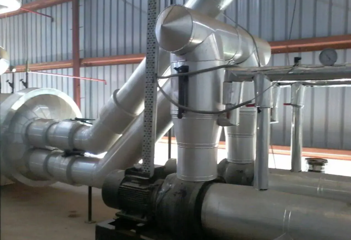
Technical Data:
| Parameter | Specification |
| Dimensions | 2000 × 1040 × 1960 mm |
| Weight | 1430 kg |
| Power Consumption | 3.7 kW |
2. Nitrogen Generation System
PSA Nitrogen Generators – NL42
Quantity: 2 Nos.
The nitrogen generation system operates on Pressure Swing Adsorption (PSA) technology, producing high-purity nitrogen by separating atmospheric gases using molecular sieves.
Working Principle
- Compressed air passed through dual adsorption columns
- Oxygen is adsorbed → nitrogen delivered to chambers
- Continuous operation through alternating adsorption/regeneration cycles

Technical Specifications:
| Parameter | Specification |
| Air Supply Pressure | 8 barg |
| Nitrogen Production | 54.9 m³/hr @ 99% purity |
| Dimensions | 900 × 1550 × 2070 mm |
| Weight | 600 kg |
Operating Conditions
- Oil Content: < 0.003 mg/m³
- Dew Point: < +3°C
- Air Purity: < 0.01 μm particles
- Operating Temperature: 18–20°C
3. Gas Distribution & Control System
Triple Header System
Quantity: 3 Nos.
- Centralized distribution of CO₂ scrubbing and nitrogen injection
- Equipped with pneumatic butterfly valves with double-acting actuators
- Ensures efficient and controlled gas distribution across chambers
Pressure Control & Safety Accessories
Manometers (Qty: 20 Nos.)
- Range: 25 mm water column
- Monitoring of pressure variations in chambers
PVC Flap Valves (Qty: 20 Nos.)
- Size: 100 mm
- Protection against overpressure and vacuum conditions
Pressure Breathing Bags
- PVC with nylon reinforcement
- Compensates pressure fluctuations during operation
4. Gas Analysis System
Portable Gas Analyzer – Oxycarb 6
Quantity: 1 No.
A high-precision portable analyzer designed for accurate measurement and monitoring of O₂ and CO₂ levels in CA chambers.
Key Features
- High accuracy & long-term stability
- Temperature-compensated measurements
- Real-time graphing & data logging (SD card)
- Touchscreen interface with intuitive controls
- Battery backup > 10 hours
Specifications:
| Parameter | O₂ | CO₂ |
| Range | 0–25% | 0–10% |
| Accuracy | < 1% FS | < 1% FS |
| Response Time | < 10 sec |

5. Central Gas Analysis System
Multiplex Plus Analyzer
Quantity: 1 No. (for 20 rooms)
A centralized gas analysis system designed for continuous monitoring of O₂ and CO₂ levels across multiple CA chambers.
System Components
- Touchscreen PLC control system
- High-precision O₂ & CO₂ sensors
- Dual diaphragm sampling pumps
- Automatic calibration system
- Electronic flow monitoring
Technical Data
| Parameter | Specification |
| O₂ Range | 0–25% |
| CO₂ Range | 0–10% |
| Accuracy | ±0.2% |
| Power Supply | 230 VAC |
| Dimensions | 600 × 600 × 1810 mm |
6. Computerized Control System
CA Plant Computer System
Client has to provide a dedicated industrial computer system for complete monitoring, control, and data management of the CA facility.
Features
- Real-time display of all parameters
- Historical data logging (up to 365 days)
- Graphical trend analysis
- Alarm indication for deviations
- Printing & reporting capabilities
Software
- Operator-defined setpoints for O₂, CO₂, RH
- IMPORTED CA CHAMBERS SLIDING DOOR
Qty: 20 Nos for CA Chambers
Size: 2200 mm X 3600 mm X 120 mm
Reciprocating Compressor

Evaporative Condenser

AIR COOLING UNITS

High Pressure Refrigerant Receiver


